Some Basics and Construction Ideas
Almost every experiment with microwaves will require some way to measure the amplitude or power. Once again, we encounter a very large number of commercial options from which to choose, but practicality dictates only a few. Among these, two stand out for the experimenter. Analog devices AD8318 and AD8362 provide excellent means of measuring microwave power. These devices are logarithmic amplifiers with input ranges of 1 > 4000 MHz and amazing low-level sensitivity.
Why a logarithmic amplifier? Power measurements are typically done in units of decibels (dB) which describes power measurements in terms of logarithms. This may seem overly complicated, but the practicality of this treatment is worth the effort. Logarithms provide a means of treating both large and small numbers on a scale that is easily visualized. This is particularly important in power measurement which often involve very large ranges of numbers, for example 1 to billions or much more. There is another reason for this topic.
Microwave technology is routinely described in terms of dB’s so users must be familiar with the concept. Keep one fact clear in your head. Engineers are human just like the rest of us and they are always looking for ways to simplify their lives. The use of logarithms or simply logs is one common example. Chemists, physicists, and astronomers have done the same.
For those of you unfamiliar with the math or just a bit rusty, a brief review will be presented. The logarithm (or log) of number N is defined as follows:
Log(X) = N where X = 10N
For example, the log(100) = 2 or X = 102. It is important to notice that in terms of logs 100 is only 2. Likewise 1000 is 3 and a billion is 9. The same holds for power measurements. In addition, the use of logs changes multiplication into addition and division into subtraction, again simplifying the work.
The unit decibel or dB is defined as the ratio of two power measurements. Specifically
X in decibels = 10 log (P2/P1) or 10 log (Pout/Pin)
Multiplication by the 10 simply makes the range of numbers more user friendly. For example, log of 6 is 0.435, multiplication by 10 makes it 4.35 for us humans.
A complication can enter the picture when the something you read seems to ignore the fact that the decibel is a ratio. That is, you always need two numbers, but one appears to be missing. For example, you may run across the statement that the RF output was 2 dB. The solution to the dilemma is in conventions developed by people working in the field. In the case of dB’s, the convention is that the measurements are made relative to 1 watt. In other words P1 or Pin is equal to one and could just as well be left out of the equation. An additional notation is used frequently, and this is dBm. In this case P1 is taken to be 1 milliwatt and P2 is measure in milliwatts. So if the statement you are reading indicates that the power at the output is 2 dBm that simply means that the power is 1.6 milliwatts at the output (10log(1.6/1) = 2). Generally, the conversation just ends with the 2 dBm and the conversion is left as an exercise to the beginner.
As we work through the experiments the reader will become very familiar with the use of dB and dBm. It will become “second nature”.
The AD8318 Logarithmic Amplifier
It is possible to buy the AD8318 from vendors like Mouser Electronics and Digi-key but for the purpose of the experiments proposed it is a better idea to buy the IC already mounted on a PC board with an SMA connector. Working at microwave frequencies can be a construction challenge because of inherent inductance and capacitance of the components and the mounting technique. Complete circuit boards are available for under $20 on e-Bay. Most come indirectly from China but the shipping times are shrinking and a little advanced planning (buy 2) will help things move along at a good pace.
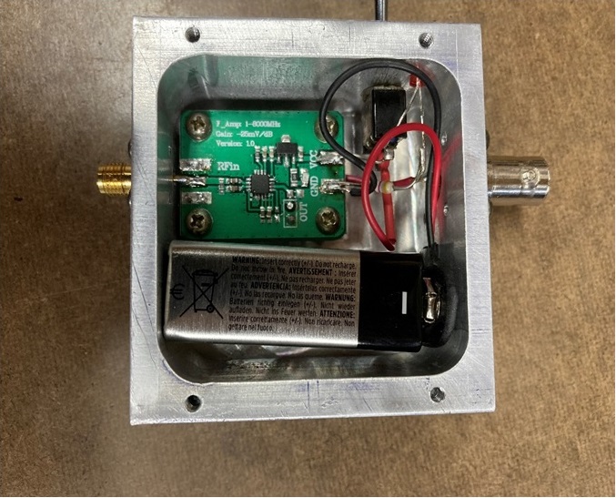
Figure 3.1. Commercial PC board with AD8318 mounted in an aluminum housing with switch and battery.
Figure 3.1 shows a typical commercial board mounted in an aluminum box with a battery, LED and on/off switch. The board originally came with the SMA connector on the board (left side). This was unsoldered carefully and a bulkhead SMA connector was mounted on the exterior of the box. The PC board was mounted on aluminum standoffs high enough to allow a direct connection to the SMA center connection. All the bolts and screws provide an adequate ground.
A bulkhead BNC connector was provided for the output (DC voltage). The BNC connector was chosen because it is compatible with many voltmeters along with a banana plug to BNC adapter. The LED was included to help remind the user that the unit was powered up. The AD8318 is power hungry and uses a bit over 60 mA when in use.
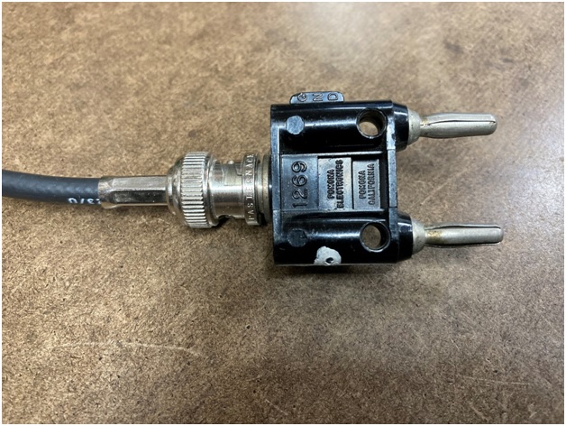
Figure 3.2. BNC to Banana Plug compatible with most voltmeters (3/4” spacing).
Why the aluminum box and the labor intensive construction? The author is a strong proponent of good solid construction. In this case, the calibration of the unit was in question and this construction, typical in microwave components, assured things would not move around. In addition, the module is a fundamental measuring component and is expected to get a lot of use.
Keep in mind that the power monitor has no frequency selection. It picks up a very wide range of frequencies, it is very sensitive, and RF interference is a potential problem. A metal box and good coaxial cables should put the experimenter in control of what the module actually measures. Frequency selection can be added but it is not need in the experiments described in this chapter.
In this particular construction, the box was milled out of a solid aluminum bar as an experiment. This strategy is labor intensive and not recommended. A die cast aluminum box available on the internet is a better option. Shop carefully for a good price. One company that has a good inventory of sizes and very good prices is Polycase.
Battery usage can be a problem if the battery is not sized properly for the application. A typical 9 volt alkaline battery has a 500 milliamp-hour capacity. Energizer claims 610 milliamp-hour for their product. The AD8318 has an operating current of 60 milliamps. This translates into about 10 hours of intermittent use. The above design should provide adequate operating time and because everything is in an aluminum box it should be fairly protected from RF interference.
Why the added construction difficulty of a 4-screw bulkhead mount. Both BNC and SMA connectors rely on a twisting motion to make the connection. If nuts and washer mounted connectors are used they often come loose after use. The 4-screw connectors will not. In commercial construction the BNC connectors are mounted in round holes with one flat side to prevent rotation. This, unfortunately, is not easy for the DIYer to reproduce. The aim is simple and reliable building techniques so that you are not constantly fixing your equipment instead of experimenting.
The AD8362 Logarithmic Amplifier
Like the AD8313 this logarithmic amplifier is available on a PC board essentially ready to go and is shown is Figure 3.3. Only a power supply is required. In order to make the amplifier robust enough for routine (translate rough and tumble) work, the amplifier was mounted in an aluminum box. In this example, a commercial die cast box (from Polycase) was chosen that was large enough to hold the PC board and batteries.
While the construction strategy for this amplifier and the one above was very similar a few differences should be noted. The AD8313 PC board, labeled “F-Amplifier” has a 7805 voltage regulator on the board which allows batteries with voltages above 7-8 volts to be used. The choice, in the above example, was a 9 volt battery which is very comfortable electronically with the regulator. The AD8362 PC board used (labeled “TruPwr Detector”) did not have a regulator and the AD8362 requires a power supply between 3.3 and 5.5 volts (not over). Three ordinary AAA batteries provide 4.5 volts and are a good solution to the supply problem.
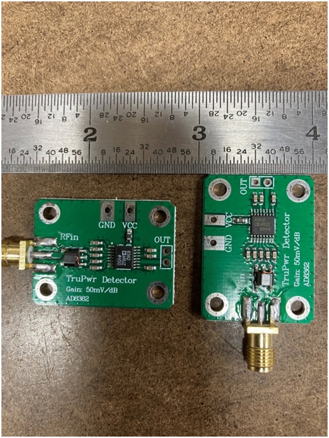
Figure 3.3. AD8362 Detector Amplifier as received.
The finished product is shown is Figure 3.4. The bulkhead connectors, switch and LED are the same as the AD8313 version. The resistor is a current limiting resistor (470 ohm) for the LED.
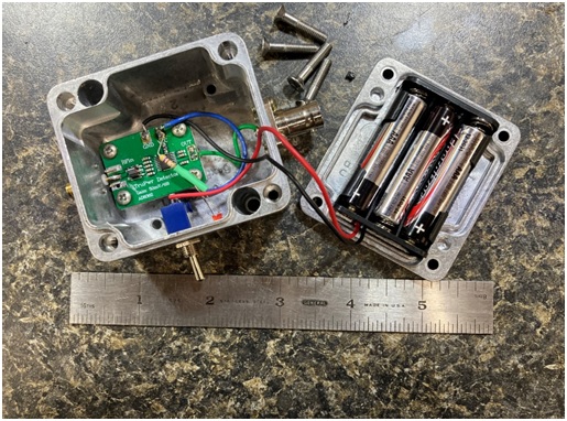
An extensive discussion of the testing and calibration can be found in the section entitle “Testing and Calibration of the Power Meters”
Warning: These amplifiers only work properly when very lightly loaded. Specifically, a voltmeter with a 10 megaohm or greater input impedance will give satisfactory results very similar to that indicated on the datasheet.
